General description of J533 - data bus diagnostic interface (Gateway):
The Gateway performs a so-called router function in the vehicle. This means it forwards the CAN messages from one bus system (such as the drive train data bus) to another (such as the convenience system data bus).
The Gateway is the central control unit in the vehicle. The Gateway is a station in all bus systems:
- Convenience system data bus
- Drive train data bus
- Infotainment data bus (optical bus)
- Extended data bus
It also has a direct connection to the dash panel insert. No sensors or actuators are connected to the Gateway, only control units by way of CAN cables.
Measured value blocks:
The measured value blocks of the Gateway indicate whether there is communication with the control units or not. The Gateway additionally contains a so-called fitting list. It additionally indicates whether the control units have entries in their fault memories. It is also possible to detect whether uncoded control units are fitted.
Coding:
All the control units of the vehicle are coded in the Gateway. Control units which are not coded cannot be diagnosed!
Control element tests:
The Gateway can launch the so-called loop break diagnosis as a control element test. Loop break diagnosis indicates which control units on the optical bus (Infotainment data bus) are defective. In this, a further distinction is made as to whether there is an electrical fault in the control unit or a fault in the fibre-optic cable.
Adaption:
No adaptions are carried out in the Gateway.
Variants:
There are different hardware variants.
a) Gateway with or without connection for J428- adaptive cruise control unit
b) Gateway with or without component protection
Component protection:
Gateways with part number 4L0 907... have component protection. Gateways with component protection must be adapted to the vehicle by way of an online link.
Coding in J533- data bus diagnostic interface (gateway):
If the control unit needs to be replaced but it is no longer possible to read the coding of the defective control unit, the new Gateway must be coded.
The following list is intended as an aid to rapid coding of the Gateway. The optional extra classification relates to the German market.
01 - Engine electronics
11 - Engine electronics II
61 - Battery control
02 - Gearbox electronics
42 - Door electronics, driver side
52 - Door electronics, passenger side
62 - Door electronics, rear left
72 - Door electronics, rear right
03 - Brake electronics
13 - Adaptive cruise control
53 - Parking brake
34 - Adaptive suspension
05 - Entry and start authorisation
15 - Airbag
25 - Immobilizer
55 - Headlight range control
65 - Tyre pressure monitor
75 - Emergency call module
06 - Seat adjustment, passenger side
16 - Steering wheel electronics
36 - Seat adjustment, driver side
46 - Convenience system central module
56 - Radio
66 - Seat/mirror adjustment
76 - Acoustic parking aid
07 - Operating/display unit
17 - Dash panel insert
27 - Rear display/operating unit
37 - Navigation
47 - Sound system
57 - TV tuner
67 - Voice control
77 - Telephone
08 - AC/heating electronics
18 - Additional/auxiliary heater
28 - AC operating unit rear
38 - Roof electronics
09 - Electronic central electrics
19 - Data bus diagnostic interface
69 - Trailer function
6C - Rear-view camera system
1D - Driver identification
0E - Media Player position 1
1E - Media Player position 2
2E - Media Player position 3
3E - Media Player position 4
4E - Display/operating unit rear right
5E - Display/operating unit rear left
0F - Radio tuner digita
1F - Radio tuner satellite
4F - Electronic central electrics II
00 - Steering angle sender
Always fitted
Always in 10- or 12-cylinder petrol engines or 8-cylinder TDI
Always fitted
Only fitted with automatic
Always fitted
Always fitted
Always fitted
Always fitted
Always fitted
Optional extra (identifiable by radar button at front)
Always fitted
Always fitted
Always fitted
Always fitted
Always fitted
Optional extra (always fitted with Xenon lights)
Optional extra (selectable from MMI Car menu)
Optional extra
Optional extra
Always fitted
Optional extra
Always fitted
Always fitted
Optional extra (identifiable by rear sensors)
Always fitted
Always fitted
Optional extra (selectable from MMI)
Always fitted
Optional extra (selectable from MMI)
Optional extra (voice control selectable sound menu from MMI)
Optional extra (selectable from MMI, telephone cradle fitted)
Always fitted
optional extra (in diesel vehicles always fitted; with petrol engines identifiable on MMI)
Optional extra (fitting location: vehicle interior at rear)
Always fitted
Always fitted
Always fitted
Optional extra (electrical socket at rear)
Optional extra
Optional extra
Optional extra (in glove box left side tray)
Optional extra (in glove box right side tray)
Optional extra (satellite radio or digital radio)
Must not be coded
Always fitted
Always fitted
Measured value blocks in J533 - data bus diagnostic interface:
This description applies to part number 4E0xxx.
The following measured values are displayed (the words in brackets indicate the possible results):
Measured value block 001:
Wake-up wire dash panel insert - data bus diagnostic interface (passive/active)
Convenience system data bus (no readout/bus idle)
Infotainment data bus (no readout/bus idle)
Drive train data bus (no readout/bus idle)
Measured value block 002:
Vacant
Vacant
Vacant
Status of loop break diagnosis wire (0 = Low, 1 = High approx. 5 V)
In the remaining measured value blocks the following results may be entered:
Result: Meaning:
No readout Control unit not coded in gateway
0 No signal/communication or control unit in sleep mode when ignition off
1 Signal/communication (in control units of the drive train data bus this status is also if there is mutual shorting between the CAN-High and CAN-Low wires)
Sl.Ind. Control unit ready to sleep
1-wire One-wire mode (only possible in convenience system data bus control units)
One-wire One-wire mode (only possible on convenience system data bus)
Two-wire Two-wire mode
Measured value block 125:
Engine electronics (no readout/0/1/Sl.Ind.)
Gearbox electronics (no readout/0/1/Sl.Ind.)
Brake electronics (no readout/0/1/Sl.Ind.)
Dash panel insert (no readout/0/1/Sl.Ind.)
Measured value block 126:
Engine electronics II (no readout/0/1/Sl.Ind.)
Airbag (no readout/0/1)
Power steering (no readout/0/1/Sl.Ind.)
Headlight range control (no readout/0/1)
Measured value block 127:
Parking brake (no readout/0/1/Sl.Ind.)
Distance control (no readout/0/1)
Empty
Empty
Measured value block 130:
CAN convenience system data bus (one-wire/two-wire)
Central electronics (no readout/0/1/1-wire/SI.Ind.)
Convenience system central module (no readout/0/1/1-wire/SI.Ind.)
Driver door electronics (no readout/0/1/1-wire/SI.Ind.)
Measured value block 131:
Front passenger door electronics (no readout/0/1/1-wire/SI.Ind.)
Rear left door electronics (no readout/0/1/1-wire/SI.Ind.)
Rear right door electronics (no readout/0/1/1-wire/SI.Ind.)
Driver seat adjustment (no readout/0/1/1-wire/SI.Ind.)
Measured value block 132:
Automatic parking system (no readout/0/1/1-wire/SI.Ind.)
Rear seat adjustment (no readout/0/1/1-wire/SI.Ind.)
Tyre pressure monitor (no readout/0/1/1-wire/SI.Ind.)
Steering wheel electronics (no readout/0/1/1-wire/SI.Ind.)
Measured value block 133:
Battery control (no readout/0/1/1-wire/SI.Ind.)
Air conditioner/heater electronics (no readout/0/1/1-wire/SI.Ind.)
Entry and start authorisation (no readout/0/1/1-wire/SI.Ind.)
Driver identification (no readout/0/1/1-wire/SI.Ind.)
Measured value block 134:
Additional/auxiliary heater (no readout/0/1/1-wire/SI.Ind.)
Roof electronics (no readout/0/1/1-wire/SI.Ind.)
Central electronics II (no readout/0/1/1-wire/SI.Ind.)
Trailer function (no readout/0/1/1-wire/SI.Ind.)
Measured value block 135:
Front passenger seat adjustment (no readout/0/1/1-wire/SI.Ind.)
Rear AC operating unit (no readout/0/1/1-wire/SI.Ind.)
Special function (no readout/0/1/1-wire/SI.Ind.)
Vacant
Measured value block 140:
Radio (no readout/0/1)
Navigation (no readout/0/1)
Telephone (no readout/0/1)
Voice control (no readout/0/1)
Measured value block 141:
Sound system (no readout/0/1)
TV tuner (no readout/0/1)
Emergency call module (no readout/0/1)
Operating and display unit (no readout/0/1)
Measured value block 142:
Operating and display unit rear (no readout/0/1)
Operating and display unit left (no readout/0/1)
Operating and display unit right (no readout/0/1)
Media player position 1 (no readout/0/1)
Measured value block 143:
Media player position 2 (no readout/0/1)
Media player position 3 (no readout/0/1)
Media player position 4 (no readout/0/1)
Vacant
Measured value block 144:
Radio tuner digital (no readout/0/1)
Vacant
Vacant
Vacant
Measured value block 200:
Vacant
Voltage term. 30
Voltage term. 15
Vacant
Dash panel left (left-hand drive):
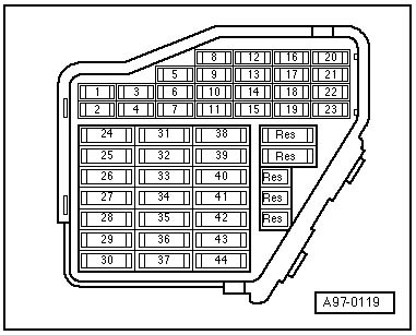
5: Terminal 30, data bus diagnostic interface control unit -J533 and control unit in dash panel insert -J285
7: Terminal 30, diagnostic coupling -T16
8: Terminal 15, diagnostic coupling -T16
10: Terminal 15, data bus diagnostic interface -J533
The J533 data bus diagnostic interface (Gateway) is located behind the glove box.
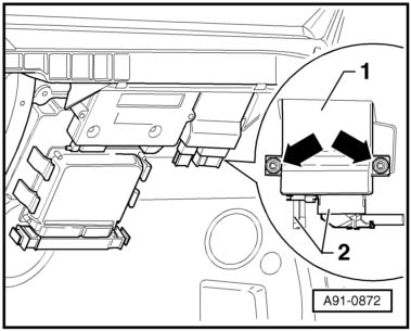
The Gateway is secured by two bolts and has an optical Most connector and an electrical connector.
Symptoms in event of loop break:
1. In the event of a loop break diagnosis of Most control units is not possible.
2. If control units of the convenience system and drive train data buses have fault entries such as
R - Radio, No signal/communication,
R78 - TV tuner, No signal/communication
there is probably a loop break.
Possible fault causes:
- Defective voltage supply to a Most control unit (fuse defective or voltage supply cut due to cable break)
- A Most control unit defective
- Open circuit in optical cable
Recommended fault finding procedure:
a) Check the fault entries in the Gateway. If the fault entry: >Optical data bus, defective< be present, the following faults may have occurred:
- Optical cable between upstream control unit and Gateway defective
- Upstream control unit defective
For the sequencing of the control units in the Most loop refer to the Fitting Location document.
b) Then check the control units fitted in the boot at the rear left.
Sequence:
- Withdraw the voice control module from the radio and check whether the loop works again.
- Check the voltage and the fuses of the control units.
- Replace a control unit with the optical replacement control unit VAS 6186. When unplugging the Most connectors from the control unit, observe whether the red light on the connector lights up. Check if the Most loop is working again by starting an MMI application (radio, TV tuner or CD).
- Run through the above procedure with the other control units in the Most loop.
c) Check whether the voltage supply to the telephone (fitted under the driver seat) is OK. Jumper the telephone using VAS 6186. Check whether the loop is working.
d) Finally check the Most control units fitted behind the glove box (Gateway, head unit):
- Check the voltage and the fuse of the head unit
- Check whether light is being emitted
Note:
It is possible to replace the two control units with the VAS 6186, but this does not help the fault finding process.
Pin assignment at J533 - data bus diagnostic interface:
Pin 1 Terminal 30, fuse 5
Pin 2 Terminal 30, fuse 5
Pin 3 Wake-up wire (to dash panel insert)
Pin 4 Loop break diagnosis wire
Pin 5 Vacant
Pin 6 Convenience system data bus, CAN-High
Pin 7 Vacant
Pin 8 Drive train data bus, CAN-High
Pin 9 Dash panel insert data bus, CAN-High
Pin 10 Vacant
Pin 11 Diagnosis CAN, CAN-High
Pin 12 Vacant
Pin 13 ACC data bus (Extended-CAN), CAN-High
Pin 14 Terminal 31 (battery negative)
Pin 15 Terminal 31 (battery negative)
Pin 16 Terminal 15
Pin 17 Vacant
Pin 18 Vacant
Pin 19 Convenience system data bus, CAN-Low
Pin 20 Vacant
Pin 21 Drive train data bus, CAN-Low
Pin 22 Dash panel insert data bus, CAN-Low
Pin 23 Vacant
Pin 24 Diagnosis CAN, CAN-Low
Pin 25 Vacant
Pin 26 ACC data bus (Extended-CAN), CAN-Low
There is also a Most socket for connection of the optical data bus.
Вперед, только вперед...
Информация о блоке 19 - Gateway
Опубликовано: 23 ноября 2014