Источник: Microcontroller Projects
An alphanumeric low cost LCD Display is very essential for may small and big projects to Display various type of information. Hitachi HD44780 Chipset based 16x2 char LCD is Really very cheap and easily available in the local market.Project Description:-
In this project we are going to learn various things about this chip set and displaying text on this LCD. The HD44780 16x2 char LCD screen Use 4 bit parallel interface with backlight.
This Primary Objective in this project are:-
1. Displaying "Hello Word!! LCD " message on the scree.
2. Interfacing The LCD to the Microcontroller Using 4 Bit Mode.
3. Generating and Displaying Custom Char on the LCD Screen. click here for custom char
Operation
as i have mentioned before this type of lcd are connected to microcontroller using parallel 8bit or 4bit lines.
using 8 bit method is quite simple but take 8 lines (for data or command)+ 3 control signal total 11 line , i guess few small microcontrollers don't even have that much of I/O lines ,so in 4 bit mode total 7 lines (sometimes 6 ) are required . in this tutorial i will show you with both of the methods .
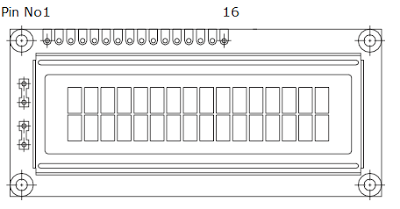
Pin description
| PIN NUMBER | SYMBOL | FUNCTION |
| 1 | Vss | GND |
| 2 | Vdd | + 3V or + 5V |
| 3 | Vo | Contrast Adjustment |
| 4 | RS | H/L Register Select Signal |
| 5 | R/W | H/L Read/Write Signal |
| 6 | E | H → L Enable Signal |
| 7 | DB0 | H/L Data Bus Line |
| 8 | DB1 | H/L Data Bus Line |
| 9 | DB2 | H/L Data Bus Line |
| 10 | DB3 | H/L Data Bus Line |
| 11 | DB4 | H/L Data Bus Line |
| 12 | DB5 | H/L Data Bus Line |
| 13 | DB6 | H/L Data Bus Line |
| 14 | DB7 | H/L Data Bus Line |
| 15 | A/Vee | + 3.5V for LED/Negative Voltage Output |
| 16 | K | K Power Supply for B/L (OV) |
in 8 bit mode all the Data line DB0 to DB7 are being used for transferring the the data to lcd but in 4-bit mode only 4 line form DB4 to DB7 are being used to transfer the 8 bit wide data in two peaces one after another .
we can't display any data on the lcd until all the required internal command register of the lcd are not being properly initialized.
to know every thing about this lcd controller .. you can go through it's data sheet
click here to download HD44780 data sheet
so now we will learn how to initialize the lcd.
LCD Commands
Clear Display
clear and place the cursor in the first position (address 0). The bit I / D to 1 by default.
|
RS
|
R / W
|
DB7
|
DB6
|
DB5
|
DB4
|
DB3
|
DB2
|
DB1
|
DB0
|
|
0
|
0
|
0
|
0
|
0
|
0
|
0
|
0
|
0
|
1
|
Return the cursor to Home
Place the cursor in the home position (address 0) and make the display starts to move from its original position. The contents of the RAM display data (DD RAM) remains unchanged. The address of the RAM for display data (DD RAM) is set to 0.
|
RS
|
R / W
|
DB7
|
DB6
|
DB5
|
DB4
|
DB3
|
DB2
|
DB1
|
DB0
|
|
0
|
0
|
0
|
0
|
0
|
0
|
0
|
0
|
1
|
X
|
Entry Mode in Set
Set cursor moving direction and specify that the display moves to the next position of the screen or not. These operations are performed during reading or writing of the DD RAM or CG RAM. To view usually set bit S = 0.
|
RS
|
R / W
|
DB7
|
DB6
|
DB5
|
DB4
|
DB3
|
DB2
|
DB1
|
DB0
|
|
0
|
0
|
0
|
0
|
0
|
0
|
0
|
1
|
I / D
|
S
|
Display ON / OFF Control
Turn on or off by turning ON / OFF both the LCD (D) as the cursor (C) and whether or not this last flash (B).
|
RS
|
R / W
|
DB7
|
DB6
|
DB5
|
DB4
|
DB3
|
DB2
|
DB1
|
DB0
|
|
0
|
0
|
0
|
0
|
0
|
0
|
1
|
D
|
C
|
B
|
Cursor or Display Shift
Move the cursor to move the LCD without changing the memory contents of the display data DD RAM.
|
RS
|
R / W
|
DB7
|
DB6
|
DB5
|
DB4
|
DB3
|
DB2
|
DB1
|
DB0
|
|
0
|
0
|
0
|
0
|
0
|
1
|
S / C
|
R / L
|
X
|
X
|
Function Set
Set the size of interface with the data bus (DL), number of lines in the LCD (N) and character type (F).
|
RS
|
R / W
|
DB7
|
DB6
|
DB5
|
DB4
|
DB3
|
DB2
|
DB1
|
DB0
|
|
0
|
0
|
0
|
0
|
1
|
DL
|
N
|
F
|
X
|
X
|
Set the CG RAM Address
The LCD module defined in addition to all the ASCII character set allows the user to define 4 or 8 characters. The composition of these characters is saved to a CG RAM memory called up to 64 bytes. Each user defined character consists of 16 or 8 bytes that are stored in successive positions of the CG RAM.
Using this instruction sets the CG RAM memory address from which the bytes will be stored that define a character. Running this command all the data that is subsequently read or write this memory made from CG RAM.
|
RS
|
R / W
|
DB7
|
DB6
|
DB5
|
DB4
|
DB3
|
DB2
|
DB1
|
DB0
|
|
0
|
0
|
0
|
1
|
CG RAM Address
|
|||||
Set the DD RAM Address
The characters or data to be displayed is stored in a memory called RAM DD then move on to the screen.
Using this instruction sets the address of DD RAM memory from which data will be stored to be displayed. Running this command all data being written to or read then they will from the DD RAM memory.
8Fh addresses 80h to 16 characters correspond to the first row and addresses C0h to CFH to 16 characters of the second row, for this model LCD.
|
RS
|
R / W
|
DB7
|
DB6
|
DB5
|
DB4
|
DB3
|
DB2
|
DB1
|
DB0
|
|
0
|
0
|
1
|
DD RAM Address
|
||||||
Read Busy Flag and Address
E l LCD module takes some time to execute instructions, at which time you should not send another instruction. This flag has a BUSY (busy) indicating that an instruction is being executed.
This reading instruction reports the status of the flag as well as providing the address counter value of the CG RAM or DD RAM according to the latest that has been used.
|
RS
|
R / W
|
DB7
|
DB6
|
DB5
|
DB4
|
DB3
|
DB2
|
DB1
|
DB0
|
|
0
|
1
|
BF
|
Address DD RAM or CG RAM
|
||||||
Write data to CG or DD RAM
Command to write to DD RAM memory the data to be presented on the screen in ASCII code.
Also written to CG RAM memory bytes to generate user-defined characters.
Previously DD RAM memory addresses or CG RAM memory where you want to write data.
|
RS
|
R / W
|
DB7
|
DB6
|
DB5
|
DB4
|
DB3
|
DB2
|
DB1
|
DB0
|
|
1
|
0
|
Byte ASCII character or graphic
|
|||||||
Read Data from CG RAM or DD RAM
Command to read data stored in DD RAM, ASCII code.
Likewise, read CG RAM memory bytes of user-defined characters.
Previously, memory addresses or memory DD RAM CG RAM you want to read the data.
|
RS
|
R / W
|
DB7
|
DB6
|
DB5
|
DB4
|
DB3
|
DB2
|
DB1
|
DB0
|
|
1
|
1
|
Byte ASCII character or graphic
|
|||||||
Connection Diagram
DOWNLOAD SOURCE CODE and Firmware
the Software is written with avr studio 5.0 and with AVR gcc GNU compiler
click here to download: ---- 4 bit mode